Dr. John A. Robertson, CEO, InfoSight Corporation
1. THE NEED
ISO 9000 and increasingly stringent customer traceability requirements now force tubular product manufacturers to better identify their product. The identification must include slowly changing lot information (such as API grade, manufacturer, size, wall, heat etc.) plus variable joint specific information such as test results, length and weight.
Today, identification of most large diameter tubular product is being done by manual I.D. paint stenciling. The joint specific variable information is then added by spraying through a selected portion of a stencil, or it is chalked on. I.D. stenciling is visible from the open end of stacked product and does not significantly contaminate the product.
There are significant tracking and inventory benefits if the identification markings also include a bar code. This can been accomplished by using an adhesive backed paper or vinyl label which is printed using thermal transfer or dot matrix printers. Unfortunately, the use of a paper or vinyl label on the protected and visible (when stacked) I.D. surface may not be acceptable for pipeline product. Customers are reluctant to place tubular product into service if it contains adhesive labels which may become detached in service. Labels affixed to the O.D. are quickly scraped off by handling equipment and are hidden in stacks.
Manual stencils are labor intensive and lack bar code capability. Adhesive labels can provide bar codes and they could be applied automatically, but they are a potential contaminant and may not survive the high (600 'F) [320'C] temperatures of subsequent O.D. coating operations. What is needed is a non-contaminating, fully automated I.D. marking technology which will survive the process and which provides high contrast and high resolution marks suitable for standard bar codes, variable plus fixed information, and even logos.
2. THE LASER SOLUTION
Marking on the curved I.D. surface may be accomplished using a specially directed and focused laser beam.
Direct surface marking using high power YAG (green, visible) lasers can discolor the tube's surface but will not produce the high contrast black/white markings required by bar codes. Also, YAG lasers are less than ideal in that they require rather complete shielding of the marked area (eye safety) and they require periodic flash lamp replacement. Therefore, direct surface marking using YAG lasers is not practical.
3. MARKER SPECIFICATIONS
| Basecoat Color | Black |
| Basecoat Thickness (wet) | Approximately 2 mil inch (.05mm) |
| Topcoat Color | White |
| Topcoat Thickness (wet) | Approximately 2.8 mil inch (.07mm) |
| Patch Width | Approximately 4 inches (100mm) |
| Patch Length (into product) | Approximately 6 inches (152mm) |
| Marked Zone | Approximately 3 inches X 4.75 inches (76mm X 120mm) |
| Minimum Line Width | Approximately 12 mil inch (.3 mm) |
| Laser Type | CO2 (Sealed) |
| Laser Power | 50 watt |
| Coating Extend | 2.5 seconds |
| Coating Time (Black) | 1.5 seconds |
| Tack Dry (Black) | 3.0 seconds |
| Coating Time (White) | 1.5 seconds |
| Tack Dry (White) | 2.0 seconds |
| Laser Extend | 2.5 seconds |
| Laser Marking | 18.0 seconds (approx. 1.25 seconds / square inch) |
| Laser / Coater Retract | 3.0 seconds |
| Total Cycle Time | 34.0 seconds |
By comparison, the ( sealed) C02 laser emits a beam in the near infrared which can be made eye safe without complete (Class 1) sealing, and it has very long operating life (typically more than 10,000 operating hours) without preventative maintenance. Unfortunately, the C02 laser at reasonable (non-cutting) power levels does not mark the bare metal. It can, however, mark an applied paint patch.
Excellent C02 laser marking contrast can be obtained by applying a black basecoat patch (to compensate for non-black product) and then applying a white overcoat which can be ablated away by the focused C02 laser beam thereby exposing the buried black layer. It is unnecessary to fully dry either coat prior to laser marking. In fact the rapid boiling of residual solvents in a tacky coating tends to "clean up" the ablation zone and thereby increases the "full black" marking speed.
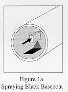
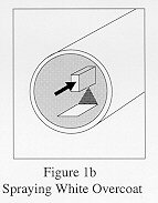
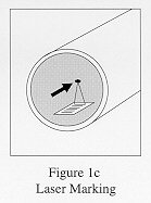
Figure 1 presents the painting/laser marking sequence. The paint coats are applied using conventional air nebulized fan spray nozzles. Laser marking is performed while the two layer patch is drying.
The resultant laser marked "painted label" is dry and hard within 3 minutes and can survive 600'F [320'F] curing operations (for 10 minutes). The marking, being on the I.D. is protected while it dries. O.D. marks would require hot air drying assist after marking and prior to either conveyor or roll table handling. A short walking beam handler might be appropriate after marking.
Note that it is also possible to laser-mark a white patch only (no black patch) on the surface of hot steel (>750'F) [>400'C] using a different type of water based heat-curing white paint which which dries immediately and blackens upon lasing.
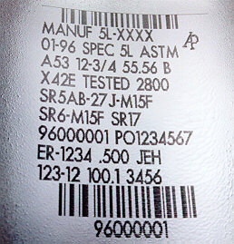
Figure 2
Figure 2 presents the general arrangement of the prototype marking with the specifications listed on the previous page (MARKER SPECIFICATIONS).
4. BAR CODE AND LOGO MARKING
An important advantage of this marker is its ability to image high quality bar codes. This means that the bar edges are sharp, the bar/space widths are within ANSI specifications, and the print contrast signal (ratio of black to white reflectivity in the visible red) is greater than 90%.
This technology cannot mark line widths less than about .012 inches (.3 mm). This means that the smallest bar "x" dimension (narrowest line or space) must be larger than .012 inches (.3 mm). Robust codes should utilize bars which are (near integer) multiples of this minimum line width.
In this first application, an 8 digit all numeric tracking number is encrypted in a picket fence (circumferential) code 128C symbology using "x"= .0 1 8 inches (.4 mm). Such a code is 2.25 inches (57 mm) long and requires a .25 inches (6 mm) clear white area at each end. This code fits on a nominal 3 inches (76 mm) wide patch.
Logos such as the API symbol are stored in the marker's non-volatile memory and can be scaled and imaged at any label location.
5. APPLICATION HINTS
- An I.D. of 9.5" (241 mm) is currently marked by the equipment as shown in Figure 2.
- A minimum I.D. of 7" (178 mm) could be probably be accommodated (with a redesigned head)
- The product must remain absolutely stationary during the raster scanning marking time. Anti-rocking arms may be required.
- Keep the marked area and data as small as possible. A single bar code and corresponding man-readable string on a 4" x 1/2" (100 mm x 13 mm) patch could be sprayed and marked in less than 8 seconds.
- The product must be clean and dry to provide for good paint adhesion. Hot air guns at a previous station have proven to be suitable surface preparation in this application.
- The process uses solvent based paints with their inherent MSDS, handling and storage concerns (same problems as spray gun stencils/paints). Due to water's reflectivity in the infrared, water based coatings are not suitable in ambient temperature applications.
- Marking fumes and overspray/vapors need to be vented (same order of magnitude as spray gun stenciling- this may require a permit in some jurisdictions). Area ventilation is required.
- The customer must have laser safety "awareness" (Class 4 laser requirements). Safety glasses should be worn in the immediate area of the marker.
6. EXTENSIONS OF THE TECHNOLOGY
Smaller patches containing only a "license plate" tracking bar code and associated man-readable string can be applied quickly. Such patches could be applied to smaller tubular product on their O.D. surfaces. It is even possible to image the end of thick-walled product.
Laser markable coatings are available which can be sprayed directly onto hot (400OF to 1500'F)[200'C to 800'C] product (one coat) and then immediately marked black. Laser marking times are increased to about 2 seconds/square inch (.31 seconds/cm2) at 1500'F (800'C). Marking of cast product immediately following casting is certainly possible.
7. CONCLUSION
We have shown that a focused C02 laser can mark programmable, high contrast, high resolution identification on the I.D. of cold tubular product if a two layer solvent based painted patch is applied first. The paint patch need not be fully dry prior to marking. This permits production rate marking in one station. O.D. marking can be done using similar techniques but drying of the patch prior to handling will be required. Hot product can be marked using a single layer patch. Direct bar code identification of tubular goods can now be accomplished without an adhesive label.
Download the PDF whitepaper.