Dr. John A. Robertson, CEO, InfoSight Corporation
Traceability, quality and inventory control improve when bar codes are applied early in the casting and rolling areas, and scanned downstream . Databases can then be accurately created and updated . Piece history and inventory accuracy are assured. A robust hot mill bar coding system requires special labels, special attachment techniques, and an understanding of the unique requirements of the hot mills.
Bar code identification is preferable to using only man readable characters because automatic identification with bar codes virtually eliminates misreading and transposition errors . In the mill environment , manual reading and entry errors frequently occur, as often as once in every 300 readings.
Computerized databases are only as accurate as the data they are fed. Bar codes can reduce the reading errors to one in several million readings. Accurate bar code reading can be done anywhere in the mill using relatively inexpensive industry
standard bar code scanners.
The following discussion has the objective of assisting in the design and implementation of a system. The goal is to facilitate automatic identification data collection through a system which:
- Provides robust , high contrast standard bar codes on hot products.
- Permits those codes to be read at distances typically found in storage yards (10 to 14 ft.).
Bar Codes
Standard bar codes consist of dark (light absorbing) bars of differing widths marked on a white (reflective) background . The bars have different separations creating the familiar picket fence codes. The data are encrypted in both the bar widths and the separations between bars. Hidden is the fact that bar codes use different symbologies . Most commercial industry standard bar code scanners can transparently read or decode all standard symbologies without adjustment.
To obtain a bar coding system that works reliably both in the mill and storage yards, the following conditions should be met:
- Codes and tags which are as physically large as is practical . Mill products are large and dirty, and difficult to get close to. A minimum bar width of 1 mm (.040") is suggested. This minimum bar or space dimension in called the "X" dimension .
- Select optimum symbology for the required data. The encoding of the same number of decimal digits using three of the more common symbologies is illustrated in Fig. 1. For equal code lengths , either the interleaved 2 of 5 or Code 128 permit considerably larger bars than Code 39 and would, therefore, be more tolerant of dirt and scraping. In general , the use of short , all decimal digit tracking numbers will enhance bar code performance.
- Bar Codes should provide high contrast between the dark bars and the white background (Fig. 2 and 3). The Print Contrast Signal ( PCS) is a measure of the relative reflectivity of the background vs. the absorbency of the bars. The PCS should be as close to 1.00 as possible with 0.85 being a minimum. The tags must provide high PCS, even after exposure to high temperatures and outside weathering.
- Bar edges should be distinct and the bars should contain a minimum number of voids. The scanner will perform reliably only if the code is clean. Tag stock should not scale or produce flaking. This usually requires stainless stock ( especially at temperatures > 1600 deg. F).
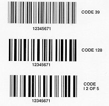
Fig. 1- Code symbology.
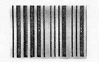
Fig.2 - Bar code with poor edges and voids. PCS < 0.7.
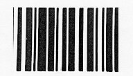
Fig. 3 - Bar code with clean edges without voids, PCS > 0.85.
Standard practice always places a backup man-readable string on the same tag next to the code.
Bar Code Tags can be either printed on-site or preprinted (off-site) (Fig. 4 and 5). Off-site printed tags have the advantage of not requiring a printer in the mill. The next tag in the supply stack is used and its unique sequential number is linked to the piece to which it is fastened (in the computer data base).
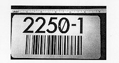
Fig. 4 - Preprinted bar code tag.
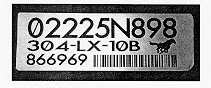
Fig. 5 - On-site printed bar code tag.
On-site printed tags can, however, contain the traditional heat/cut/size/weight information and do not require a parallel computer data base. The recent development of using a C02 laser to blacken a white coated stainless tag makes on-site tag
printing more reliable because no ribbons or contact print heads are required. The special laser markable coatings are blackened deep into the coating, thereby providing robust markings which weather well.
High contrast , well defined codes with an X dimension of 0.050 in can be reliably read at about 14 feet using off the shelf ( long range) scanners. This permits an inventory of stacked slabs if the tags are placed in a position where they may be safely scanned while stacked. Recent developments in video bar code readers will permit the design of systems that read at longer distances ( 30 feet) so that verification by crane operators or slab haulers is possible.
Tag Attachment
Tag Slots - A metal strapping band can pass through a pair of slots in a tag (Fig. 6). Several mills have integrated automatic ( embossed ) tag markers /feeders with conventional banding equipment. Similar approaches could be used with bar coded tags. Manual banding (through coil eyes) can also affix such tags.
Concerns remain over losing tag identification if the band breaks or drops off. Abbreviated paint marks or dot peen markings could be added to permit manual recovery of the product's identity if the band is lost. Multiple tags on different bands (especially nonbelly bands) would significantly enhance the chances of identification survival.
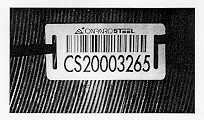
Fig. 6 - Tag with band slots.
Nails - Nails may be driven ( pneumatically or with an explosive charge) into cast shapes (slabs , blooms and billets) to attach a tag.
Some mills consider that side nailing on slabs can produce defects in the rolled products. End nailing may be preferred since this area is often sheared prior to rolling.
Virtually all nailing is done manually. Automated feeding of nails ( and explosive charges) is difficult and may prove to be unreliable and unsafe.
Plasma Welding - A recent development in tag attachment is the use of a relatively thick tag ( 1 mm) and a plasma ( shielded tip) welding torch. No additional consumables beyond argon and electric power are required. Plasma welding creates a reliable arc start path which penetrates non-conductive surface scale (Fig. 7). Plasma welding can tack the tag edge in such a way that the tag can be later easily hinged-off if desired.
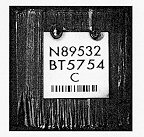
Fig. 7 - Tag attached to bilet end by plasma welding.
Resistance Spot Welding - Resistance spot welding may be practical if the product surface is clean , relatively smooth and highly conductive. Tags have been spot welded onto hot products ( < 1500 deg. F) .
Either the tag edges or spots on a coated tag must be bare for reliable electrode contact. Welding current flows between two ( copper) electrodes which are pressed firmly against these bare areas producing current flow through the tag , through the
product, and back through the tag producing two resistance spot welds at a time (Fig. 8).
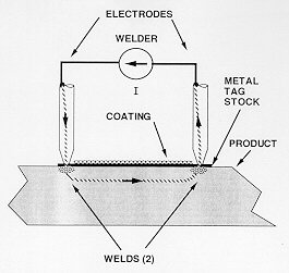
Fig. 8 - Tag attachment by resistance welding.
Resistance welding tag attachment has been successful in attaching tags to hot band coils ( both O.D. and I.D.) and plate especially edges ( Fig. 9). The coil fold-over tag has the advantage that one tag provides bar codes on both the outer wrap and the ply end.
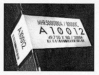
Fig. 9 - Folded tag attached to hot band coil by spot welding.
Resistance welding may be unreliable in attaching tags to slabs, particularly stainless grades which produce hard non-conductive scale, and flame cut billet ends because of roughness.
Resistance welding may be of special interest on structural shapes. In this application, a tag that is spot welded on its edges may be easily pulled off without leaving any defects (foreign matter ) upon the shape . In final use, the shape (less tag) can then be painted without requiring any preparatory grinding .
Significant contact pressure is essential for repeatable resistance welds. The requisite pressures are easily obtained by mechanical arms but may not be practical for unleveraged manual tools.
MIG welding using preforms - Conventional MIG (GMAW) welding of thin tags to heavy product sections has proven to be unreliable. The resultant weld to the product (if any) is limited to a thin rim along a hole which the arc blows in the thin tag .
Reliable MIG welding attachment can be facilitated by providing a relatively thick (3 mm) preform on the tag stock ( Fig. 10). MIG welding through a hole in the preform produces a rivet like attachment which is robust. The MIG welding wire arc is initiated on contact with clean preform and /or bare tag materials, and the ongoing metal spray will penetrate product surface scale.
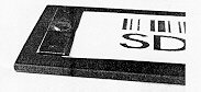
Fig. 10 - Tag with 3-mm preform attached by MIG welding.
Preforms can enable fully automated tag attachment . Automated tagging equipment that marks a preform bearing tag and then MIG welds it onto hot slab ends is now in operation. Equipment payback of less than 1 year based on labor savings alone are expected.
Direct Marking On Hot Product
It is advantageous to apply a high resolution bar code directly onto hot product without requiring a label. Recent technology provides direct marking by first applying a high temperature coating patch by a spray and then selectively blackening the patch using lasers.
The result of spraying a specially formulated 6.5" x 12" white patch upon a 1200 deg. F hot band surface and then marking that patch using C02 laser radiation is shown in Fig. 11. The resultant markings, accomplished in less than 2 minutes, include large (crane man readable) man - readable characters as well as bar codes and graphics (logo). These markings are removable in subsequent pickling processes.
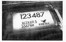
Fig. 11 - Direct marking with laser on white, sprayed patch on hot band.
Similar markings can be imaged on a slotted tag ( Figure 15) using the same marker, These tags can be band attached to tested coils after removal of a test coupon.
Extensions of this technology will permit the direct bar code marking of structural shapes , pipe , plate edges and even billets and slabs.
Download the PDF whitepaper.