Dr. John A. Robertson, CEO, InfoSight Corporation
Bar coding is one method of marking tubular products for handling during the production process. Tubes can be bar coded by several techniques, including adhesive-backed paper or polyester labels, paint spraying, and laser marking.
Why use bar coding? Keeping track of each tube using limit switches and timing (so-called "queue tracking") can be unreliable. If tubes are switched among several possible paths by manual intervention, the confusion increases, and a tube's identity becomes uncertain.
Automatic identification in the form of bar codes on tubular products can help tube producers control their products and processes. Because of its typical 99.99 percent accuracy, automatic identification almost eliminates the errors inherent in manual entry methods.
Bar coding provides:
1. Improved traceability of each piece back to the parent material.
2. Automatic data collection during processing.
3. Improved documentation of nondestructive testing (NDT) test results.
4. Inventory accuracy and improved efficiency in taking inventory.
5. Improved shipping accuracy.
6. Field identification.
7. ISO tracking certification.
Marking Spray-Painted
Binary Codes
Traditional bar code symbols require accurate bar and space widths. Although it is not practical for many reasons to spray accurate bar widths in the mill, it is practical to spray "nominal" bar widths with accurate (edge-to-edge) spacings.
Figure 1 shows two coded tubes on which the bars have been applied using a single fan spray nozzle that is switched on and off at electric resistance welding (ERW) mill line speeds.
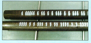
Figure 1
On these tubes, binary codes have been applied using a single fan spray nozzle that is switched on and off at ERW mill line speeds.
This code is large enough (40 inches long with 1/4-inch-wide, 2-inch-high bars) to survive most mill rolls and can be read even if a portion of each bar is scuffed off. The large size of the code is appropriate to the size of the product, making it easy to locate and read.
Although practical to apply, such binary codes contain fewer permutations than standard bar codes with an equal number of bars (remember, all of the bar width data was lost). Each binary code shown in Figure 1 encodes about 2,700,000 unique numbers. If such a code were applied sequentially-for example, every 8 feet on a 100 feet per minute (FPM) continuously operating ERW mill-the sequence would repeat (wrap) every five months. This is acceptable for tracking product while it is inside the mill, where a given tube would not likely remain more than five months before it is reidentified.
Reading Spray-Painted
Binary Codes
Spray-painted binary codes are not industry-standard symbols. Reading them requires special readers that employ vision technology. CCD cameras with electronic shutters can transfer "stop-action" video image frames into analyzing electronics, which then locate the code anywhere in the video frame and decode the image to provide the read result data output.
Because such readers search every video frame in real time, it is practical to "find" codes on tubes as they move through a V-roll conveyor line either by using several multiplexed cameras looking at the tube from various radial positions or by spiraling the tube as it moves past one camera.
If the tubes are stationary, they must be rotated to bring the code into view while the camera is scanned back and forth to locate the code longitudinally. Positioning the tubes for automated reading within existing equipment can be accomplished by adding pop-up spin rollers at stationary locations or by canting the conveyor rolls to provide spiral rotation in conveyors.
Laser Marking
Standard Bar Codes
An industry standard bar code mark of high contrast may be applied directly onto tubular product by first painting a patch and then marking it with a laser (typically a sealed C02 laser). Figure 2 shows a tube marked on its outside diameter (OD). The marked area can also include human-readable characters and graphics such as logos.
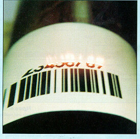
Figure 2
This tube has been laser-marked with standard bar code on its OD.
Two methods are currently used to make the direct mark:
1. A patch of two coats of solvent-based paints is sprayed onto the tube, and a laser is used to mark the patch by selectively ablating or darkening one of the coats. The paints may be siloxones so that the resultant "label" will survive the high temperatures (about 600 degrees Fahrenheit) typical of downstream pipeline epoxy-coating operations.
2. In the case of hot or cast products such as seamless pipe or ductile iron, a single-coat patch of water-based ceramic paint is sprayed onto the product. That patch can be laser-blackened while the product is still hot. Drying is instantaneous.
Each of these approaches can produce a direct label on either the inside diameter (ID) or OD of tubular products at one station at tube mill production rates. Complete, hardened drying of the patch on ambient-temperature product may take about 5 to 10 minutes.
Tubes with marks applied on the protected ID (see Figure 3) may be rolled or conveyed before the direct label dries. However, ambient-temperature tubes marked on the OD must be dried before conveying. This may require a short walking beam with heated air directed on the patch at each walk.
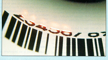
Figure 3
Tubes with marks applied on the protected ID may be rolled or conveyed before the direct
label dries.
The laser marking time depends on the marked area. Typically, a 2- by 6-inch patch can be spray-applied and marked within about 20 seconds.
Safety
Laser safety is an important issue. Since tubes must be moved in and out of the marker location quickly, complete shielding of the laser marking area is impossible, making the marker a Class 4 device under 21 CFR (J).
Fortunately, the required laser power levels are low (less than 50 watts), the duty cycles are low (less than 30 percent), and the invisible infrared C02 laser radiation (10.6-micron wavelength) is much less dangerous than visible laser radiation.
As a result, with proper design and safety interlocks, laser markers become Class 1 (not considered hazardous) if humans cannot get within about 1 meter of the marking spot when the marking laser is on.
Reading Laser-Marked
Standard Bar Codes
Direct laser markings usually include standard bar codes that can be read using off-the-shelf scanners. Reading and tracking is simplified when the bar code's narrowest bar or space (the "x dimension") is as wide as possible. So, for a given patch area, it is important to encrypt as little data as possible in the bar code and to choose the most appropriate symbology.
For example, if you can get by with eight numbers (99,999,999 different tubes), the narrowest line on a 3.6-inch patch will be .037 inch wide when using code 128C (numbers only) symbology. If you encrypt the same eight characters using code 39 (full alphanumeric) symbology on the same patch size, the line width will be reduced to .019 inch, allowing the code to be more easily disrupted by dirt or conveyor roll scuffing.
A short license plate number can be used as an index into a comprehensive real-time database, and that database can be used rather than trying to encrypt all of the traditional data into the bar code.
Many readers (scanners) are available for standard bar codes in hand-held and fixed styles. Hand-held units with radio frequency (RF) communications capability can read bar codes on the ID manually, permitting inventory-taking in the storage yard.
Automated reading of standard bar codes by fixed scanners as the joint moves through the production process is a bit more complicated. It requires positioning the code within a relatively small scanner window.
To do this, OD codes are placed a fixed distance from a tube end that will not be cropped, and the tube is slowly rotated while it is justified on an end stop. Codes on the ID should be applied just far enough in from the tube end so that they will not be destroyed by facing operations. They can be read using an angled scanner while the product rotates against a stop.
Remember that the physically small standard bar code is indexed to one end of the tube. Tubes cannot be read if they have been rotated end for end.
Proposed Marking and
Reading in an ERW Mill
Figure 4 is a diagram of a proposed laser marking and reading system in an ERW tube mill.
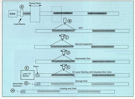
Figure 4
Shown here is a proposed laser marking and reading system in an ERW tube mill.
First, a sequential binary code is applied to the just-welded tube's OD about every 8 feet as it enters the flying cutoff (A). The use of multiple sequential codes on each tube permits later cutting of the tube without losing the identification on each piece and allows the producer to determine whether it came from the head or tail of the parent tube.
OD marking ensures that the code can be automatically read as the tube moves through existing conveyors and roll tables.
The sequential codes are linked to a real-time computer database that ultimately will contain all of the information being collected about each tube. At the flying cutoff, the database for each code is initialized to contain the skelp coil (source, heat, and chemistry), time and date, weld parameters, etc.-the data that is available just after welding.
As each tube is further processed through the mill, its binary code is repeatedly read, and the database is updated. Data from NDT weld inspection is read at B with a single fixed camera. The code is "aligned," because the weld is oriented for testing and the tube is moving longitudinally.
Manual inspections and hydrostatic test parameters are automatically appended to each tube's data record using readers at C and D. These readers must also slew longitudinally to locate a code. At manual inspection, the tube is already rolled. New pop-up spin rolls may be required at read station D just before hydrostatic testing.
When the tube reaches the end of the finishing operation, its binary code is again read at E, and the database information becomes available for final tube identification using an ID laser-marked patch applicator at F. That patch might include a standard bar code plus all other required American Petroleum Institute (API) information.
For uncoated product, the binary code can be read, and the appropriate paint stencil or die-stamped identification string can be determined and marked before shipment.
The standard bar code can be used for taking yard inventory at G and for coating, shipping, and field documentation at H using hand-held scanners.
Summary
Direct marking of bar codes on tubular product is now possible. Large binary codes on the OD are useful in the mill since they can be reliably read with automatic readers as tube moves through the existing equipment.
Standard bar codes can be applied directly onto tubular products using laser-marked, sprayed paint patches to allow manual scanning with industry-standard equipment. Direct-marked bar codes provide tube traceability and accurate database information for each piece to ensure that the correct documented product is going out the door.
Download the PDF whitepaper.